
1: Overview & The Microscope
- Page ID
- 12521
WHAT YOU’LL LEARN TO DO: Describe and identify anatomical position and locate major organs.
LEARNING OBJECTIVES
- Identify anatomical position and be able to reference it when describing anatomical locations.
- Know where to cut to create each of the following and be able to recognize the views created by a cut in each of the following:
- mid-sagittal plane
- para-sagittal plane
- frontal plane
- transverse plane
- Be able to look up anatomical nouns and adjectives for external body areas and find what they refer to.
- Apply each pair of terms to locate a structure or direct someone to a structure:
- superior/inferior
- anterior/posterior
- medial/lateral
- proximal/distal
- superficial/deep
- dorsal/ventral
- cephalad/caudal
- supine/prone
- Locate each of the following:
- dorsal body cavity
- cranial cavity
- spinal cavity
- ventral body cavity
- thoracic body cavity
- diaphragm
- abdominopelvic cavity
- abdominal cavity
- pelvic cavity
- List the major organs and identify at least two physiological roles for each of the 11 human organ systems:
- integumentary
- skeletal
- muscular
- nervous
- endocrine
- cardiovascular
- lymphatic/immune
- respiratory
- digestive
- urinary
- reproductive
- Identify each organ in the anatomical model and know its location within the model body:
- cranial cavity
- palate
- parotid salivary gland
- sublingual salivary gland
- submandibular salivary gland
- larynx
- trachea
- esophagus
- aorta left
- lung (2 lobes)
- right lung (3 lobes)
- diaphragm
- kidney
- adrenal (suprarenal) glands
- liver
- gall bladder
- pancreas
- stomach
- spleen
- large intestine
- small intestine
- appendix
- ovaries
- uterus
- female urethra
- testes
- scrotum
LEARNING ACTIVITIES
Complete the following lab activities and exercises:
- Reading: Anatomical Position and Planes
- Exercises 1.1
- Reading: Anatomical Orientation and Directions
- Exercises 1.2
- Reading: The Human Body Cavities
- Exercises 1.3
- Reading: The Human Organ Systems
- Exercises 1.4
- Reading: Parts of a Compound Microscope and How To Handle Them Correctly
- Exercises 1.5, 1.6 and 1.7
- Reading: How The Virtual Image Differs From The Real Image
- Exercise 1.8
- Making Simple But Accurate Line Drawings of Magnified Specimens
- Exercise 1.9
Anatomical Position and Planes
Anatomical Position
When anatomists or health professionals identify the location of a structure in the human body, they do so in reference to a body in anatomical position. That is, they figure out the location based on the assumption that the body is starting out in anatomical position. Anatomical position for a human is when the human stands up, faces forward, has arms extended, and has palms facing out.
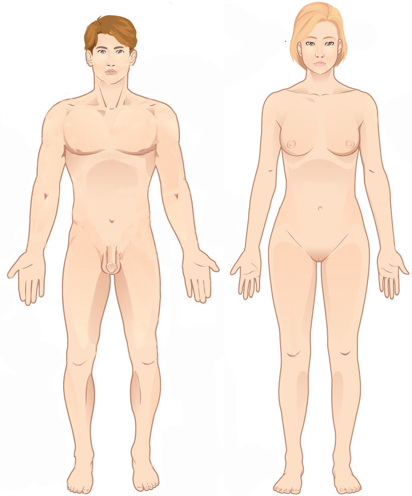
Figure 1.1: These two people are both in anatomical position.
When referencing a structure that is on one side of the body or the other, we use the terms “anatomical right” and “anatomical left.” Anatomical right means that the structure is on the side that a person in anatomical position would consider their right-hand side (not necessarily on the right of the viewer) and anatomical left means that the structure is the side that a person in anatomical position would consider their left-hand side (which likewise is not necessarily the left side of the viewer.)
Anatomical planes
To view the interior of a body, we expose the organs and structures that are visible when that body is cut open along one of four commonly used sectional planes. These planes are the different directions a body is cut to reveal different views of its internal structures.
- Frontal plane—A vertical cut that separates the front from the back of the specimen. Also known as a coronal plane.
- Transverse plane—A horizontal cut that separates the top from the bottom of the specimen. Also known as a cross-sectional plane.
- Midsagittal plane—A vertical cut down the exact center line of the specimen that separates the left half from the right half.
- Parasagittal plane—A vertical cut that is off-center that separates the left of the specimen from the right in unequal portions. It does not matter whether it is the left side or the right side that is larger, as long as they are not equal.
Figure 1.2. The different sectional planes used to expose internal structures.
LICENSES AND ATTRIBUTIONS
CC LICENSED CONTENT, ORIGINAL
A&P Labs. Authored by: Ross Whitwam. Provided by: Mississippi University for Women. Located at: http://www.muw.edu/. License: CC BY-SA: Attribution-ShareAlike
Figure 1-3. A banana person prior to being cut along transverse, frontal, and midsagittal or parasagittal planes.. Authored by: Ross Whitwam. Provided by: Mississippi University for Women. Located at: http://www.muw.edu/. License: CC BY-SA: Attribution- ShareAlike
CC LICENSED CONTENT, SHARED PREVIOUSLY
Figure 1-1. These two people are both in anatomical position.. Provided by: OpenStax College. Located at: http://cnx.org/contents/Gko70fNo@1/Anatomical-Terms. License: CC BY-SA: Attribution-ShareAlike
Figure 1-2. The different sectional planes used to expose internal structures.. Authored by: JonRichfield. Provided by: Wikipedia. Located at: https://commons.wikimedia.org/wiki/F...nnotations.jpg. License: CC BY-SA: Attribution-ShareAlike
Anatomical Vocabulary
Anatomical nouns and adjective for external body parts
Information
Like all areas of science, there is a lot of jargon associated with anatomy and physiology. Often terms are used within the field that differ from what we would name things in everyday conversation. Such jargon usually allows the specialist in the field to be more precise in what exactly they are referring to, but the jargon also can be intimidating and exclusionary. If you don’t know it, you are not in the club.
LAB 1 EXERCISE 1-1
Here are a bunch of anatomical adjectives (followed in parentheses by the noun version of the same term). For each, use your smart phone or laptop or whatever is most convenient to you to find what body part the term refers to. (Shortcut hint: the Google search engine will return definitions for words if you type “define: word” in the search box, leaving out the quotation marks.)
Write down the body part or body region next to each term. Use Figure 1.4 to help you make sure you have the correct definition but look up each definition to make sure you are being accurate.
1. Find the body part or region indicated by each of the following terms. Use everyday language to describe the part or region. (Forearm, belly, etc.)
|
Abdominal (abdomen) |
Acromial (acromion) |
||
|
Antebrachial (antebrachium) |
Antecubital (antecubitis) |
||
|
Auricle (auris) |
Axillary (axilla) |
||
|
Brachial (brachium) |
Buccal (bucca) |
||
|
Carpal (carpus) |
Cephalic (cephalus) |
||
|
Cervical (cervicis) |
Coxal (coxa) |
||
|
Cranial (cranium) |
Crural (crus) |
||
|
Digital (digit) |
Dorsal (dorsa) |
||
|
Facial (facies) |
Femoral (femur) |
||
|
Frontal (frons) |
Gluteal (gluteus) |
||
|
Inguinal (inguen) |
Lumbar (lumbus) |
||
|
Mammary (mamma) |
Manual (manus) |
||
|
Mental (mentis) |
Nasal (nasus) |
||
|
Olecranal (olecranon) |
Oral (oris) |
||
|
Ocular (oculus) |
Palmar (palma) |
||
|
Patellar (patella) |
Pelvic (pelvis) |
||
|
Plantar (planta) |
Popliteal (popliteus) |
||
|
Pubic (pubis) |
Sacrum (sacral) |
||
|
Sural (sura) |
Tarsal (tarsus) |
||
|
Thoracic (thorax) |
Umbilical (umbilicus) |
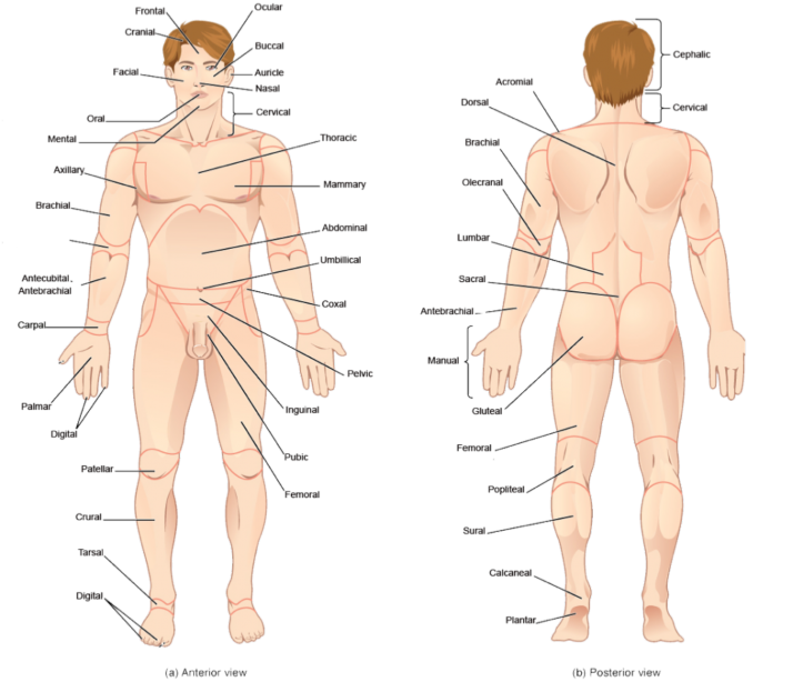
Figure 1.4. Anatomical adjectives for common surface features.
- A&P Labs. Authored by: Ross Whitwam. Provided by: Mississippi University for Women. Located at: . License: CC BY-SA: Attribution-ShareAlike
CC LICENSED CONTENT, SPECIFIC ATTRIBUTION
Figure 1-4. Anatomical adjectives for common surface features.. Provided by: OpenStax College. Located at: http://cnx.org/contents/FPtK1zmh@6.2...al-Terminology. License: CC BY-SA: Attribution- ShareAlike
Anatomical Orientation and Directions
Information
To be able to direct others to specific anatomical structures, or to find structures based on someone else’s directions, it is useful to have specific pairs of terms that allow you to orient your search with respect to the location of another, known structures. The following pairs of terms are used to make comparisons. Each term is used to orient a first structure or feature with respect to the position of a second structure or feature.
- Superior/Inferior–Equivalent to above and below when moving along the long axis of a body in anatomical position. The structure that is superior to another is above the second structure when the body is in anatomical position. A feature that is inferior to another is below the second feature when the body is in anatomical position.
- Proximal/Distal–Equivalent to near and far. Usually used to orient the positions of structures and features along the limbs with respect to the trunk of the body. A feature that is proximal to something else is closer to the limb’s point of attachment to the trunk. A structure that is distal to something else is farther away from the limb’s point of attachment. Less precisely but still occasionally used in the trunk of the body itself to indicate whether something is closer to (proximal) or farther away from (distal) something else.
- Medial/Lateral–Equivalent to towards the middle or towards the edge. Used with respect to the midline of the trunk of a body in anatomical position. A structure that medial to another is closer to the midline of the body’s trunk. A feature that is lateral to another is farther away from the midline of the trunk.
- Anterior/Posterior–Equivalent to the front and back of a body in anatomical position. A structure that is anterior to another is closer to the front of the body when the body is in anatomical position. A feature that is posterior to another is closer to the back of the body when the body is in anatomical position.
- Ventral/Dorsal–Equivalent to belly-side and back-side of a body in anatomical position. For a human in anatomical position, this pair of terms is equivalent to anterior and posterior. However, for four-legged animals in what is considered their anatomical position, the belly-side is not equivalent to the front of the animal. A structure that is ventral to another is closer to the belly-side of the body. A feature that is dorsal to another is closer to the back of the body.
- Superficial/Deep–Equivalent to closer to the surface and farther from the surface.
- Cephalic/Caudal–Equivalent to closer to the head and closer to the tail. This is more useful for four-legged animals with tails than for upright humans with only a vestigial tail.

Figure 1.5. Pairs of terms providing anatomical direction or orientation.

LAB 1 EXERCISE 1-2
- Fill in the blank with the appropriate directional term to complete the following sentences. More than one answer may be correct.
- The heart is to the lungs.
- The knee is to the hip.
- The wrist is to the hand.
- The mouth is to the nose.
- The thorax is to the abdomen.
- The thumb is to the ring finger.
- The sternum is to the heart.
- The skull is to the scalp.
- The ears are to the nose.
- Dorsal refers to the of the human body, while ventral refers to the
of the human body.
- Find the indicated structures in the diagrams provided, based on the directional terms given. The structure to find will be one of those at the end of an unlabeled line.

Figure 1.8. Anatomy of the human ear.
- Label the extensor digitorum (ED) muscle in the figure below. It is:
- Distal to the anconeus muscle
- Lateral to the extensor digiti minimi muscle
- Superficial to the Extensor pollicis brevis muscle

1
2
3
5 4
6
7
8
9
- Label the Incus in the figure below. Label only one of the empty boxes. It is:
- Superior to the lateral end of the cochlear nerve
- Medial to the malleus
- Lateral to the stapes
- Label the extensor digitorum (ED) muscle in the figure below. It is:
- Using your knowledge of the different body planes shown in Figure 1-2 (shown again below), fill in the blanks with the appropriate body plane for each of the following descriptions.

Figure 1.9. The different sectional planes used to expose internal structures.
LICENSES AND ATTRIBUTIONS
CC LICENSED CONTENT, ORIGINAL
- The plane that divides the body into anterior and posterior parts is the
plane.
- A transverse plane divides the body into and
regions.
- A or plane divides the body into right and left parts.
- A&P Labs. Authored by: Ross Whitwam. Provided by: Mississippi University for Women. Located at: http://www.muw.edu/. License: CC BY-SA: Attribution-ShareAlike
CC LICENSED CONTENT, SPECIFIC ATTRIBUTION
- Figure 1-5. Pairs of terms providing anatomical direction or orientation.. Authored by: Osteomyoamare. Provided by:
Wikipedia. Located at: https://commons.wikimedia.org/wiki/F...Directions.png. License: CC BY-SA: Attribution- ShareAlike
- Figure 1-5. Pairs of terms providing anatomical direction or orientation.. Authored by: Osteomyoamare. Provided by: Wikpedia. Located at: https://commons.wikimedia.org/wiki/F...rections_2.png. License: CC BY-SA: Attribution-ShareAlike
- Figure 1-6. Cross-section of the thigh.. Authored by: Marshall Strother. Provided by: Wikipedia. Located
at: https://commons.wikimedia.org/wiki/F...ss_section.svg. License: CC BY-SA: Attribution-ShareAlike
- Figure 1.7. Muscles of the forearm.. Provided by: OpenStax College. Located
at: http://cnx.org/contents/FPtK1zmh@6.2...ectoral-Girdle. Project: Anatomy & Physiology. License: CC BY-SA: Attribution-ShareAlike
- Figure 1.8. Anatomy of the human ear.. Authored by: Chittka L, Brockmann. Provided by: Wikipedia. Located
at: https://commons.wikimedia.org/wiki/F...man_Ear_en.svg. License: CC BY-SA: Attribution- ShareAlike
- The plane that divides the body into anterior and posterior parts is the
- Figure 1-2. The different sectional planes used to expose internal structures.. Authored by: JonRichfield. Provided by:
Wikipedia. Located
at: https://commons.wikimedia.org/wiki/F...nnotations.jpg. License: CC BY-SA: Attribution-ShareAlike
The Human Body Cavities
Information
The major cavities of the human body are the spaces left over when internal organs are removed. There are additional body cavities which we will only discuss in lecture. These are the cavities created by serous membranes–the pleural cavities, the pericardial cavity, and the peritoneal cavity–and the mediastinum.
- Dorsal body cavity–the cranial cavity and the spinal cavity in combination.
- Cranial cavity–the space occupied by the brain, enclosed by the skull bones.
- Spinal cavity–the space occupied by the spinal cord enclosed by the vertebrae column making up the backbone. The spinal cavity is continuous with the cranial cavity.
- Ventral body cavity–the thoracic cavity, the abdominal cavity, and the pelvic cavity in combination.
- Thoracic cavity–the space occupied by the ventral internal organs superior to the diaphragm.
- Abdominopelvic cavity–the abdominal cavity and the pelvic cavity in combination.
- Abdominal cavity–the space occupied by the ventral internal organs inferior to the diaphragm and superior to the pelvic cavity.
- Pelvic cavity–the space occupied by the ventral internal organs that are bordered by the bones of the pelvic girdle.

Figure 1.10. The locations of the major body cavities of the human body.
LAB EXERCISE 1-3
Fill in the blank with the appropriate body cavity
cavity.
LICENSES AND ATTRIBUTIONS
CC LICENSED CONTENT, ORIGINAL
- The two main body cavities are the and the
cavities.
- The stomach is found in the cavity.
- The heart is found in the cavity, which is part of the larger
cavity.
- The brain is found within the cavity which is part of the larger
cavity
- The urinary bladder and reproductive organs are found within the
- The two main body cavities are the and the
- A&P labs. Authored by: Ross Whitwam. Provided by: Mississippi University for Women. Located at: http://www.muw.edu/. License: CC BY-SA: Attribution-ShareAlike
CC LICENSED CONTENT, SHARED PREVIOUSLY
Figure 1-9. The locations of the major body cavities of the human body.. Authored by: Mysid. Provided by: Wikipedia. Located at: https://commons.wikimedia.org/wiki/F...avities-en.svg. License: Public Domain: No Known Copyright
The Human Organ Systems
Information
Organ systems are groups of organs within the body that can be thought of as working together as a unit to carry out specific tasks or functions within the body. The human body is most commonly divided into eleven organ systems, the ones listed below.
It should be kept in mind that these divisions are somewhat arbitrary as to which organs are included and which are excluded. Skeletal muscles attached to bones are part of the muscular system, but the smooth muscles around soft tissues are not. Skeletal muscles are attached to bones, and serve to move the bones, but bones are part of the skeletal system, not the muscular system.
It also bears remembering that no one organ system ever functions independently of the others. The nervous system sends instructions to the muscular system as to when to move particular muscles. The cardiovascular system delivers nutrients and removes wastes from the muscle fibers of the muscular system to allow them to continue to function, etc. Dividing the human body into eleven organ systems is simply a way for the human mind to organize information about what parts do what. In the body itself, the parts that need to interact do interact, regardless of which system they have been grouped into.
The eleven organ systems are shown in Figure 1-11. The figure also lists the organs in each system and some roles for each system.


Identifying the major internal organs of the body
LAB 1 EXERCISE 1-4
For each of the following organs, identify the organ system to which it belongs. There are three organs in this list which each belong to two organ systems; in those cases, list them both.
|
Brain |
Ovaries |
||
|
Cartilage |
Pancreas |
||
|
Skin |
Spleen |
||
|
Heart |
Kidneys |
||
|
Lungs |
Testes |
||
|
Mammary glands |
Gall bladder |
||
|
Thymus |
Pituitary gland |
CC LICENSED CONTENT, ORIGINAL
- A&P Labs. Authored by: Ross Whitwam. Provided by: Mississippi University for Women. Located at: . License: CC BY-SA: Attribution-ShareAlike
CC LICENSED CONTENT, SPECIFIC ATTRIBUTION
- Figure 1-10. Organ Systems, part 1.. Provided by: OpenStax College. Located
at: https://cnx.org/resources/9470e72cca...ody(Page1).jpg. Proje ct: Anatomy & Physiology . License: CC BY-SA: Attribution-ShareAlike
- Figure 1-10. Organ Systems, part 2.. Provided by: OpenStax College. Located
at: https://cnx.org/resources/9490de5610...ody(Page2).jpg. Licen se: CC BY-SA: Attribution-ShareAlike
The Parts of a Compound Microscope and How To Handle Them Correctly
Information
Many important anatomical features, especially those that function at the tissue or cellular levels, are too small to be seen by the unaided eye. The compound microscope is a valuable tool for magnifying small sections of biological material so that otherwise inaccessible details can be resolved.
There are many different types of microscopes. We shall only learn about the compound light microscope. It uses visible light to visualize the specimen, but passes that light through two separate lens to magnify the image. The compound microscopes we will use in this course are sturdy instruments but they still have a lot of moving parts. They can be damaged and broken through misuse and mishandling. A large part of learning how to use the microscopes properly involves learning how to avoid damaging it. To do that, you first have to know which parts are which. Figure 1.12 identifies the key parts of the microscope that you need to be familiar with.
In Figure 1.12, there are two compound microscopes shown. The one on the left is monocular and the one on the right is binocular. Many of the parts of the two microscopes are in slightly different locations. Get used to this. Different brands and different models of microscopes position the key parts differently.
When you first sit in front of a microscope, you should always take a second to find the key parts, especially the focus knobs, the condenser adjustment knob (if present), and the stage control knobs. When viewing a specimen, your eyes will be at the eyepieces, and if you grab the wrong knob by accident, you can lose your image at best, and damage the microscope at worst. Don’t assume you remember where the key knobs are. You may have a different microscope than last time.
When storing a microscope you should always follow this list:
- Remove any slide found on the stage and return it to the slide box.
- Rotate the smallest lens or no lens into place above the stage. Lower the stage a few turns.
- Loosely coil the cord in your hand starting near the microscope and working toward the plug.
- Hang the coiled cord over one ocular lens.
- Look at the number on the back of the microscope, return that scope to its numbered box.
- If there’s already a microscope in that numbered box, check its number and move it. If it is not numbered simply push it to the back of the box and place yours closer to the front. We have a few extra microscopes which we store in this fashion.

Figure 1.12 Some key parts of a compound light microscope.
The eyepiece
This is where your eyes will be. If the microscope is binocular, use both eyepieces. With binocular microscopes, you almost always can adjust the width of the eyepieces to ensure they fit the spacing of your eyes. The eyepiece contains the eyepiece lens, one of the two lenses doing the actual magnifying in a compound microscope.
The carrying arm
When moving a microscope, even if it is just a few inches, always pick it up by the carrying arm. Do NOT drag the microscope: pick it up. The microscope will have rubber feet that prevent it from sliding, so if you try to drag it, it will shake and vibrate and possible damage parts. Never pick up the microscope by any part other than the carrying arm. The other parts are generally much more fragile and prone to breaking if you try.
The objective lenses
Most compound light microscopes will contain three to four objective lenses that can be rotated over the slide. Sometimes these lenses are just called objectives. When a particular objective has been fully rotated into position, you will hear or feel a click as that objective locks into place. The objective lens is the second of the two lenses doing the actual magnifying in a
compound microscope, so if it is not snapped into proper position, you won’t see the proper image. Each objective lens can usually be unscrewed from its position in the rotating turret that houses it. Be careful you are rotating the turret, not unscrewing an objective. Do NOT unscrew the objectives from the turret. Each objective lens has a different magnifying power, so the image on your slide will be magnified to lesser or greater extents, depending on which objective lens you have chosen. Each objective’s magnification power will be written somewhere on the side of the objective, although sometimes it is hard to see the number. The magnification of an objective lens will always be a whole number. There will be other things written on the side of an objective, but the one that is a whole number greater than 1 will be the magnification. You can ignore everything else written there.
The stage
The stage is the platform that the slide will be clipped on to.
Stage clips
The slide will be held in place on the stage with stage clips. Most of the time, these will clip against the sides of the slide. They do not sit above or below the slide. They are spring-loaded to hold the slide edges and lock the slide in place so that the stage controls can move the position of the slide smoothly. If the slide is not clipped in place, you won’t be able to reposition the slide to find microscopic features of interest.
Stage Controls
These allow you to move your slide while you are viewing it, but only if the slide is properly clipped in with the stage clips. Always find where these are on your microscope before you start viewing your slide. They seem to never be in the same place in two different microscopes and if you just blindly grope for them while viewing your slide, you will likely do something unfortunate to your view or to the entire microscope. There are always two dials. One moves the slide left and right. The other moves the slide up and down. Sometimes they are on top of each other, as in the binocular microscope in Figure 1.12. Sometimes they are two separate dials, as in the monocular microscope in Figure 1.12. Sometimes they are above the stage, as in the monocular microscope in Figure 1.12. Sometimes they are below the stage, as in the binocular scope in Figure 1.12. Spend a few seconds to find them every time before you sit down at a microscope.
Coarse focus
This is always the larger of the two focus knobs. You should usually only need to use the coarse focus knob once for each new slide. Use it with the lowest power objective to get the specimen approximately in focus. After that, only use the fine focus knob, even after you change to a higher-power objective. Sometimes the coarse focus knob is with the fine focus knob, as on the binocular microscope in Figure 1.12. Sometimes it is separate from the fine focus knob, as on the monocular microscope in Figure 1.12.
Fine focus
This is always the smaller of the two focus knobs. This is the focus know you will use over and over again in viewing slides. Don’t change the coarse focus after using it for the first time, only change the fine focus.
Condenser adjustment
Not all microscopes have a condenser adjustment knob. If there are only two knobs, as on the monocular microscope in Figure 1.12, those two are the coarse focus and the fine focus and you only have to keep those two separate. But if there is a third knob, it is the condenser adjustment knob. As a general rule, do NOT touch or adjust this knob. It controls how far the light condenser is from the slide, which should be properly adjusted before you use the microscope. If you move it, you will have it in the wrong position. If your scope has the knob, find out where it is and avoid it.
Diaphragm
This is directly under the hole in the stage where light passes through to the slide. It is controlled by a lever which opens and closes an iris to let more or less light through the slide. In some specimens there is not much contrast between the colors and shades of the different components being magnified. Changing how bright the view is by adjusting the diaphragm can allow you to better see some of the details you are trying to magnify.
LAB 1 EXERCISE 1-5
There are compound microscopes in the large wooden boxes in the front of the room. The boxes and the scopes are numbered. Use any scope you like but please return it to the correctly numbered box. Carry out the activities listed below and fill in the blanks as you do so.
- Pick up your microscope and physically move it to a new location. Bring it close enough that you can look into it comfortably from where you are sitting. Arrange it so that the stage is facing you and the eyepiece is rotated towards you. What part of the microscope did you grab in order to pick it up and move it?
- Where are the locations of the two stage adjustment knobs on your microscope?
- Where is the location of the coarse focus knob?
- Where is the location of the fine focus knob?
- Is there a condenser adjustment knob? If so, where is it located?
- Find the diaphragm lever. Looking in the hole in the center of the stage, what happens when you move the diaphragm leverclockwise?
- Still looking down at the hole in the center of the stage, what happens when you slide the diaphragm lever counter-clockwise?
LICENSES AND ATTRIBUTIONS
CC LICENSED CONTENT, ORIGINAL
- A&P Labs. Authored by: Ross Whitwam. Provided by: Mississippi University for
Women. Located at: http://www.muw.edu/. License: CC BY-SA: Attribution-ShareAlike
- Labelled compound light microscope. Authored by: Ross Whitwam. Provided by: Mississippi University for Women. Located at: http://www.muw.edu/. License: CC BY-SA: Attribution- ShareAlike
Magnification and Resolution
Information
The reason for using a microscope is to magnify features to the point where new details can be resolved.
Magnification is the factor by which an image appears to be enlarged. It will be a whole number greater than 1 and is usually followed by an “x”, as in 10x magnification.
When you look through microscope eyepieces, you are seeing a virtual image because in reality, what you are looking at is not as large as it appears through the eyepieces, and because there can be some distortion of the image.
Resolution is the shortest distance between two points that can still be visually distinguished as separate. The resolution of a typical unaided human eye is about 200 µm. Using a microscope decreases the resolution to distances as short as 0.2 µm. Resolution is a property of the eye.
Resolving power is the ability of a lens to show two adjacent objects as discrete. Resolving power is a property of a lens.
Each lens in a microscope has a numerical aperture, or NA, value. This has to do with the angles of light that enter and exit a lens. Its applications are beyond the scope of this lab, but numerical aperture does influence the resolution possible with a particular lens, and so the NA value for the lens is usually printed on each objective. It will be a number less than 1.0, and you can ignore it for our purposes.
Each lens in a microscope also has a magnifying factor. This is the degree to which that lens magnifies an image. It will be a number larger than 1.0. For instance a 10x objective magnifies the image ten-fold. The magnifying factor for each objective always printed on it, and the magnifying factor for each eyepiece is usually printed on it. (If the eyepiece is missing a printed magnifying factor, you can usually assume it is 10x.)
The total magnification for any image viewed under a compound microscope is calculated by using the formula:
Total Magnification = eyepiece magnifying factor * objective magnifying factor
So, each time you switch objectives, you change the total magnification. Total magnification does not have units, but is usually indicated by an “x”, as in “total magnification = 100x.”
LAB 1 EXERCISE 1-6
There are compound microscopes in the large wooden boxes in the front of the room. The boxes and the scopes are numbered. Use any scope you like but please return it to the correctly numbered box. Carry out the activities listed below and fill in the blanks as you do so.
- Write down the magnification factor for the eyepiece lenses on the microscope in front of you.
- Using the microscope in front of you, write out all the words and numbers written on each objective on your microscope. There are probably three objectives, but some microscopes might have four. Start with the smallest objective and move through them in order of increasing size
Objective one:
Objective two:
Objective three:
Objective four:
- In the above list, for each objective, circle just the magnification factor for that objective. Remember, the magnifying factor is a whole number, and differs for each different objective.
- Write down the total magnification (eyepiece magnifying factor * objective magnifying factor) when using each objective on the microscope in front of you.
Objective one:
Objective two:
Objective three:
Objective four:
- If you observed two features on a slide with your naked eye that were 0.5 mm apart, how far apart would they appear to be if you observed them with the microscope in front of you, using the second objective?

LICENSES AND ATTRIBUTIONS
CC LICENSED CONTENT, ORIGINAL
- A&P Labs. Authored by: Ross Whitwam. Provided by: Mississippi University for
Women. Located at: http://www.muw.edu/. License: CC BY-SA: Attribution-ShareAlike
Setting Up a Microscope and Slide Properly
Information
All the microscopes in the lab are parfocals. That means that if the slide is in focus under one objective, it will stay largely in focus if the objective is changed. In practical terms, this means you should usually only need to use the coarse focus knob once per slide. You get the slide in focus under the lowest-power objective (where focusing is easiest), then, from that point onward, only make minor adjustments with the fine focus knobs even if you change objectives.
When you first get a new slide, you can usually determine the location of the specimen by looking at the slide while it is still in your hand. The specimen is usually a patch of color somewhere near the center of the coverslip. After you clip your slide securely onto the stage with the stage clips, use the stage control knobs to move the patch of color until it is directly over the hole in the center of the stage where the light comes through. Now when you look through the eyepieces using the lowest objective (always start with the lowest objective) you should be able to find the specimen and get it quickly in focus.
Occasionally the eyepiece or objective lenses will have specks of dirt or dust on them, making it difficult to focus on the specimen. To clean lenses, always use lens paper supplied by the lab instructor or a pure cotton swab. Do not use any other type of cloth or paper as they might scratch the lens. KimWipes are NOT lens paper, NEVER use KimWipes on glass lenses or slides. To remove dirt with lens paper, first roll up the lens paper and try to dry brush away the dirt in a spiraling motion that circles from the center of the lens out. If that doesn’t work, moisten the lens paper or pure cotton swab with blue lens cleaning solution (do not apply the water to the lens directly) and clean in a spiraling motion from the center of the lens out.
Below is a checklist for initially setting up a microscope. Every time you get a new slide, you should use this checklist.

LAB 1 EXERCISE 1-7

25
How The Virtual Image Differs From The Real Image
Information
The virtual image you see when looking in your microscope is not quite the same as the real image you would see with your eye. For one thing, it is bigger. For another thing, the orientation of the image is different. The two lenses in a compound microscope reflect the original image two times, in two different planes, while magnifying it. So what you think of as the “top” of your image is really the bottom, and what you think of “right” is really left. Usually this is not an issue at the microscopic level, but it is important to understand how the microscope is rearranging your virtual image.
LAB 1 EXERCISE 1-8
- Get an “e” slide. If it is already under your microscope, rotate the lowest-power objective into place, use the coarse focus to lower the stage, and remove the slide.
- Look at the unmagnified “e” on the slide by eye. Rotate the slide around in your hand so that the “e” is right side up. Now clip the slide onto the microscope stage with the stage clips so that the “e” is facing you right side up when you look at it with your unaided eye.
- In the right-hand circle below, draw what the “e” looks like when you are looking at it right side up. Assume the circle below is the size of the entire coverslip. Draw the “e” you see unaided in the correct proportion to the coverslip. (The unmagnified “e” will take up a tiny portion of the coverslip area.)

- Clip the slide into your microscope stage so that the “e” is still facing you right side up. Follow the checklist in Lab 1 Exercise 1-7 to ensure you are setting up the microscope properly for use, but stay on the lowest power objective. Get the “e” into your field of view and in focus.
- In the left-hand circle above, draw what the “e” looks like when viewing it through the microscope under the lowest-power objective. Under the circle, write the total magnification of the image.
- When viewed under a microscope, how is a specimen
rotated?
- Look at the stage and slide directly (not through the eyepieces.) Move the stage control knob that causes the slide to move away from you on the stage, then move it back to its original position.
- Now move the stage control knob the exact same way you just did, but view the “e” through the eyepiece. When the stage is moving away from you, what direction does the virtual image appear to be
moving?
- Again, look at the stage and slide directly (not through the eyepiece.) This time, move the stage control knob that causes the slide to move to your right, then move it back to its original position.
- Now move the stage control knob the exact same way you just did, but view the “e” through the eyepiece. When the stage is moving to your right, what direction does the virtual image appear to be
moving?
- The field of view is the entire area you can see when looking through an eyepiece. Use the stage control knobs to move the virtual image of your “e” to one side of the field of view. Keep most of the “e” in the field of view, but move it to one side or the other.
- Now switch to the next-power objective. (Do not skip.) To get to the next-power objective, and not the highest-power objective, which way did you have to rotate the objectives, clockwise or counter-
clockwise?
- Using only the fine focus knob (you do NOT use the coarse focus knob on any objective other than the lowest objective), get the “e” in focus.
- When moving to the next objective, which part of the field of view do you zoom in on?
- Move away from the eyepieces and look at the distance between the slide and the bottom of the objective. Rotate back to the lowest power objective. Now rotate to the next objective (do not rotate to the highest-power objective by accident). Now rotate to the third-highest objective. What happens to the distance between the slide and the bottom of the objective as you rotate to higher power
objectives?
- With the third-highest power objective still in place, how much space is there between the slide and the bottom of the
objective?
- Notice there is a danger of smashing the objective lens into the slide if you were to use the coarse focus. Why are you instructed to only use the coarse focus with the lowest- power objective?
Making Simple But Accurate Line Drawings of Magnified Specimens
Information
You do not have to be a great artist to make a diagram of the cells and structures you see under a microscope. You only have to be careful to draw something that is approximately the same size and shape as what you see. Follow the following guidelines:
- Only draw what you actually see. Even if you expect to see something, if it is not there you should not draw it. Do not base your drawings on what the textbook or some other source tells you should be there. Do not draw things in the shapes that texts or other sources tell you to expect unless you actually see those shapes.
- Keep things as simple as possible. Draw strong unbroken lines. Avoid shading or cross- hatching unless there is a very good reason to add them.
- Feel free to simplify reality by leaving out unnecessary details. Draw what is of interest, but leave out background material, debris, or any other distracting items. Just be careful that, if you are leaving something out, that it isn’t something that is an important part of what you are drawing.
You should always have a basic understanding of what you are looking for before looking in the microscope. Tissues and other microscopic specimens can be confusing and cluttered. If you know in general what you are looking for, and, sometimes more importantly, what you are not looking for, it will make it much easier to find what you want to draw and it will make it much easier to decide how to draw it.
Just remember, what you see under the microscope may look quite different from the perfect specimens that are usually found in the figures put into textbooks and websites. Use the idealized images to track down what you are looking for, but draw the specimen as it actually is, regardless of your expectations.
For instance, in most textbooks, neurons, the most common cell found in nervous tissue, are drawn to look like variations of the drawing in Figure 1.13A.

Figure 1.13. A. A typical diagram of a neuron. B. An actual neuron.
In the typical diagram of a neuron that appears in texts and on websites, there usually is a clear nucleus, and often a nucleolus visible, too. Sometimes organelles such as mitochondria are visible (there are none in Figure 1.13A.) The dendrites are typically short and branched. There almost always is a single, easily-identifiable axon that is longer than all the dendrites and that branches as it ends.
Figure 1.13B shows an actual neuron as viewed through a microscope. If you view enough neurons through enough different types of microscopes, you can eventually create a composite diagram that incorporates features from many specimens to present a “typical” neuron, but it is unlikely that if you view a single neuron you will see everything in Figure 1.13A. In fact, often actual specimens look very little like their textbook counterparts. Draw what you see, not what you think you are supposed to see. Just make sure you are looking at what you are supposed to be finding (for instance, a neuron and not a piece of dirt or cell debris), and then draw it as it is.
In the case of the actual neuron in Figure 1.13B, there is no nucleus visible, there is maybe one large projection and one small projection you could call dendrites – but there aren’t many projections – and neither of the projections are branched. There is one long thin projection that is probably an axon, and it is not branched.
If you draw what you see, you end up with a drawing like the one in Figure 1.14B. It does not look like a textbook neuron, but it is a reasonable representation of what is there in this case.

Figure 1.14. A. An actual neuron. B. A drawing of Figure 1.14 A’s neuron.
Most students feel they “cannot draw” and are reluctant to sketch what they are seeing under a microscope. You don’t let your lack of artistic skills stop you.
- Draw an outline that approximates the item you want to draw. Don’t obsess about making it match perfectly. Approximate is ok.
- Try to get the proportions approximately right. If something is half as big, or as third as big, as something else, make it that way in the drawing, too.
- Do not draw everything you see. Improve on reality by only drawing the parts of the specimen you are interested in. You do not have to draw every bit of debris or dirt. Decide what the important parts of your specimen are and draw only those.
- Do not use shading or cross-hatching unless there is a very good reason to do so. It will actually make it easier to understand your drawing if you stick to drawing just outlines. It will also be easier and quicker to draw.
LAB 1 EXERCISE 1-9
- Get a human blood smear slide. Rotate your lowest power objective into place on your microscope.
- Follow the checklist in Lab Exercise 1-7 until you are viewing the blood smear under your 40x objective.
- You will see mostly red blood cells. They will probably be pinkish and they will be the circles without nuclei. Occasionally, some will appear to have blank circles in their centers, but these are not nuclei. If you search around your slide using your stage controls, you will find the rare circular cells with nuclei. These are white blood cells. There will be less than one white blood cell for every 100 red blood cells. These white blood cells will probably be light blue or grey and have purple or dark blue nuclei. Their nuclei will not always be round.
- Find a section of your slide with two or more white blood cells among all the red blood cells.
- In the circle below, draw four or five representative red blood cells (do not draw all the red blood cells you see) and draw all the white blood cells in your field of view. Pay careful attention to drawing the white blood cell nuclei as accurately as possible.
- Do not remove or change the position of your slide until one of your lab partners has verified that your white blood cells are drawn accurately. Introduce yourself to a partner and ask for their help.

LICENSES AND ATTRIBUTIONS
CC LICENSED CONTENT, ORIGINAL
- A&P Labs. Authored by: Ross Whitwam. Provided by: Mississippi University for Women. Located at: http://www.muw.edu/. License: CC BY-SA: Attribution-ShareAlike
- Figure 1.14B. A drawing of Figure 4.3 A's neuron.. Authored by: Ross Whitwam. Provided by: Mississippi University for Women. Located at: http://www.muw.edu. License: CC BY-SA: Attribution-ShareAlike
CC LICENSED CONTENT, SHARED PREVIOUSLY
- Figure 1.13A. A typical diagram of a neuron.. Authored by: Jonathan Haas . Located
at: https://commons.wikimedia.org/w/inde...curid=18271454. License: CC BY-SA: Attribution-ShareAlike
CC LICENSED CONTENT, SPECIFIC ATTRIBUTION
- Figure 1.13B. An actual neuron; Figure 4.3A. An actual neuron. Authored by: W. Clay Spencer, Rebecca McWhirter, Tyne Miller,
Pnina Strasbourger, Owen Thompson, LaDeana W. Hillier, Robert H. Waterston, David M. Miller III. Located at: http://dx.doi.org/10.1371/journal.pone.0112102. License: CC BY: Attribution
When storing a microscope, you should always follow this list:
-
- Remove any slide found on the stage and return it to the slide box.
- Rotate the smallest lens or no lens into place above the stage. Lower the stage a few turns.
- Loosely coil the cord in your hand starting near the microscope and working toward the plug.
- Hang the coiled cord over one ocular lens.
- Look at the number on the back of the microscope, return that scope to its numbered box.
- If there’s already a microscope in that numbered box, check its number and move it. If it is not numbered simply push it to the back of the box and place yours closer to the front. We have a few extra microscopes which we store in this fashion.

A&P Labs. Authored by: Ross Whitwam. Provided by: Mississippi University for Women. Located at: http://www.muw.edu/. License: CC BY-SA: Attribution-ShareAlike